

Liquid cooling leaks: what a CDU manifold leak takes out, and how to model it
A coolant distribution unit (CDU) separates the facility water from the coolant that runs to the racks, and pumps that coolant through manifolds to cold plates, rear doors or immersion tanks. When a manifold leaks, the loop loses coolant and pressure; leak detection should close that manifold's isolation valves, so only the racks it serves lose cooling and their chips throttle or shut down while the rest of the loop runs on. How much coolant reaches the floor depends on how fast the leak is detected and isolated, and how much the isolated section holds.
Rack power calculator
Enter the devices in one rack with their typical draw (measured if you have it, otherwise an estimate per model). Results are estimates.
| Device | Qty | Watts each |
|---|---|---|
| Rack load | |
|---|---|
| Breaker capacity (80 % rule) | |
| Each PDU, normal | |
| Surviving PDU if one feed fails |
1. The loop, piece by piece
A liquid-cooled row is two loops joined at the CDU. ASHRAE TC 9.9’s liquid cooling terms are the ones most specifications use: the facility water system (FWS) runs from the chillers, dry coolers or towers to the CDU; the technology cooling system (TCS) runs from the CDU to the IT equipment.
| Part | What it does | When it fails |
|---|---|---|
| Facility water (chiller, dry cooler, heat exchanger) | Takes the heat away from the CDU | Every CDU it feeds warms up |
| CDU | Heat exchanger, pumps, reservoir, filters and controls for flow, pressure, temperature and level | The whole loop it serves loses flow, unless another CDU carries it |
| Row and rack manifolds | Split the CDU’s supply to each rack and collect the return | A leak drains the loop until its valves close |
| Isolation valves | Cut a manifold, a row or a CDU out of the loop | Stuck open: a small leak becomes a loop leak |
| Hoses and quick disconnects | Connect each server to the rack manifold | The most handled joints in the loop |
| Cold plates, rear doors, tanks | Take the heat from the chips, the rack exhaust or the immersed server | The device overheats; coolant may reach electronics |
Three kinds of liquid cooling, three leak profiles:
- Direct-to-chip (dlc): cold plates on the CPUs and GPUs, fed from a rack manifold through hoses with quick disconnects. Many joints, inside the rack, near the electronics, and water-glycol coolant conducts. The rest of the server (memory, drives, power supplies) still sheds heat to air: DC Sim’s catalog record for a liquid-cooled rack-scale GPU system puts 70 % of its heat into the liquid.
- Rear-door heat exchanger (rdhx): a coil in the rack’s rear door cools the exhaust before it reaches the room. Water stays out of the servers; a leak is at the back of the rack and on the floor.
- Immersion: servers sit in a tank of dielectric fluid. A drip on a board is not the hazard; spills, fluid handling during maintenance and the tank’s own heat exchanger are.
Leaks in one paragraph: they start at the joints (quick disconnects, hose fittings, manifold ports, cold-plate fittings, CDU pump seals); they show up as falling loop pressure and reservoir level at the CDU, or on rope and spot sensors; the response is detect, isolate the manifold, move the workloads, make the wet equipment safe.
2. Where leaks start
- Quick disconnects: connected and disconnected at every server swap. Worn seals, debris on the coupling and a half-seated connector are typical causes; dripless couplings reduce the spill when they are opened.
- Hose and fitting joints: crimps, threads and push fittings, especially where a hose is bent hard or pulled during maintenance.
- Manifold joints and valves: ports, welds and valve stems along the rack manifold.
- Inside the server: fittings at the cold plates. These leak onto the board.
- At the CDU: pump seals, filter housings, the heat exchanger.
- During filling, venting and service: the loop is open and fittings are handled; check every joint you touched before you walk away.
Condensation is not a leak, but it trips the same sensors. Keep the coolant supply above the room’s dew point; below it, pipes sweat and rope sensors alarm with no leak at all. A slow fall in the CDU’s reservoir level with no water in sight is the opposite case: a small leak somewhere the sensors do not reach, or trapped air working its way out.
3. What a manifold leak does, step by step
- Coolant escapes. Loop pressure and the CDU’s reservoir level fall. The CDU often sees the pressure drop or level alarm before anyone sees water.
- Detection. Rope sensors along the manifold or in the drip tray, spot sensors under the CDU, or the CDU’s own alarms.
- Isolation. The manifold’s valves close, automatically on a leak alarm or by hand. Everything downstream of them loses flow.
- The servers on that manifold. With no coolant flow, cold-plate temperatures rise quickly; the chips throttle, then shut down on thermal protection. Coolant that reached a board can short it.
- The rest of the loop runs on, if the valves isolated the right section and the CDU holds pressure.
How much reaches the floor is roughly leak rate × time to isolate, plus whatever drains from the isolated section. Faster detection and smaller isolated sections are the two levers.
A CDU stopping is a different failure: no leak, but every rack on its loop loses flow at once, unless a second CDU on the same loop carries the load.
4. A short leak runbook
- Confirm the location: which sensor zone alarmed, and do the CDU’s level and pressure agree.
- Isolate: check that the manifold’s valves closed; close them by hand if not.
- Protect the workloads: move or drain the jobs on the isolated racks before thermal protection does it for you.
- Make it safe: cut power to wet equipment before anyone touches it.
- Contain and clean: absorbent and drip trays; handle the coolant as its safety data sheet says.
- Repair and recommission: fix the joint, refill, vent the air, pressure-test, then open the valves.
- Record it: the timeline, the volume, the racks, the workloads and the cause.
The leak what-if below gives you steps 2 to 4 per manifold before the first leak.
5. Design choices that limit a leak
- Isolation valves per rack manifold, so a leak takes out one rack instead of a row.
- Leak detection on every manifold and under every CDU, wired to close the valves.
- Drip trays under manifolds and CDUs, and nothing electrical below a joint where you can avoid it.
- N+1 CDUs on a shared loop, sized so one can stop.
- CDU pumps on UPS: coolant pumps without battery stop with the utility, and a cold plate with no flow heats up fast.
- Negative-pressure loops keep the coolant below atmospheric pressure, so a breach draws air in instead of pushing coolant out.
- CDU readings in your monitoring: supply and return temperature, flow, pressure and reservoir level, with alarms to whoever is on call.
6. Model the loop in the template’s Liquid sheet
Template v1.5 adds an optional Liquid sheet. Each row adds a CDU, a manifold or both to a loop. Required: loop, type and serves.
| loop | type | serves | cdu | capacity_kw | supply_c | return_c | flow_lpm | coolant | secondary | manifold |
|---|---|---|---|---|---|---|---|---|---|---|
| L1 | dlc | R01-R04 | CDU-1 | 400 | 30 | 40 | PG25 | Dry cooler 1 | ||
| L1 | dlc | R01 | M-R01 | |||||||
| L1 | dlc | R02 | M-R02 | |||||||
| L2 | rdhx | R09-R12 | 120 | Chiller 1 |
How the importer reads it:
type:dlcandimmersionmake the served racks liquid-cooled;rdhxhangs a rear door behind every served rack and splits that sheet row’scapacity_kwbetween them (30 kW per door above).serves: rack names, rows, or ranges such asR01-R04.flow_lpm: left empty, it comes from capacity and temperature difference, capacity × 60 ÷ (4.0 × (return − supply)): 400 × 60 ÷ (4.0 × 10) = 600 L/min for CDU-1. Without temperatures, 1 L/min per kW.secondary: the node the CDU hands its heat to. A name with “chill” becomes a chiller, anything else a dry cooler or heat exchanger; a chiller named by a rear-door row becomes the doors’ chilled-water source.manifold: each named manifold gets its own valve. Racks of a loop that no manifold row names share one manifold, so name a manifold for every set of isolation valves you really have.cdu: may name a CDU in the Devices sheet with a catalog model; that row becomes the CDU instead of an IT device. A loop with no CDU row gets one sized at 1.25 × its liquid heat, marked assumed.coolantandreturn_care read for the flow only; the model keeps no coolant type.
If the Power sheet has mechanical boards (names with mech, cooling, HVAC or CDU), the CDUs and cooling units run from them, and DC Sim flags CDU pumps that are not on UPS. The Excel template page lists every sheet and column.
7. Run the leak what-if
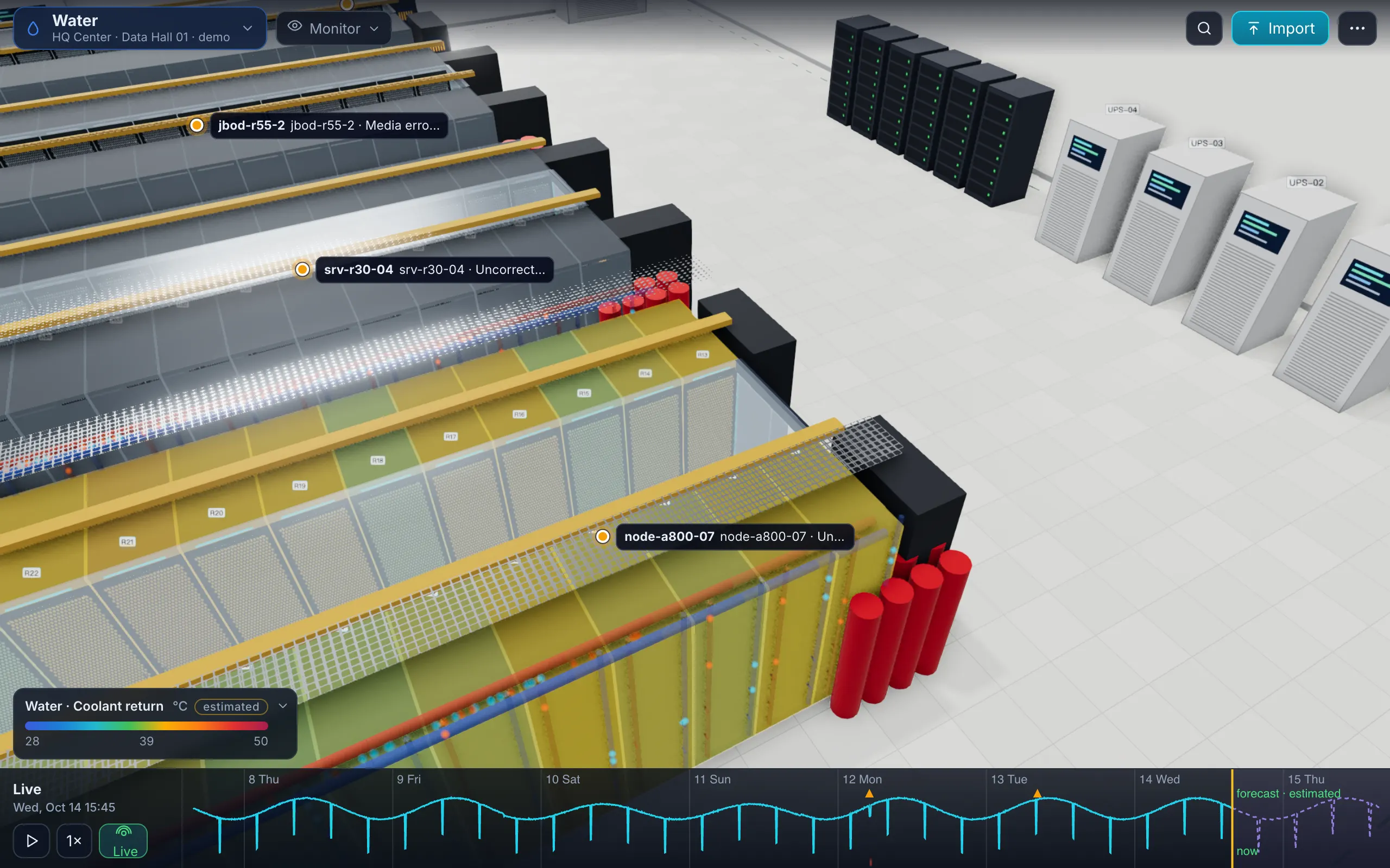
In DC Sim’s Water view, select a manifold and choose Simulate a leak. The manifold’s valve closes when its leak is detected (noted as assumed), so only its racks lose cooling. The scenario reports, next to an untouched baseline:
- the litres released (estimated),
- the racks isolated and the devices throttled or tripped,
- who is on that manifold: racks, devices, workloads and tenants,
- tokens lost on GPU nodes: the tokens per second they were producing, summed over the scenario.
In the AI hall demo, a leak at manifold R02 releases 1.4 L (estimated), the valve isolates the manifold, 2 devices with 16 GPUs throttle or trip, and 7.8 M tokens are lost. The clip below is that run. A CDU failure is in the same scenario library, and air-cooled racks next to the liquid row sit in the same model.
Liquid and thermal figures come from a zonal model, not CFD, and are labelled estimated. Because Design and Simulate use the same model, you can leak every manifold of a hall that is not built yet, which is the cheapest time to move a valve. Tokens per kWh explains tokens as a cost of failure, and Simulate lists the whole scenario library.
6 steps
List the loops, CDUs and manifolds
One Liquid sheet row per CDU and per manifold, each with its loop, its type (dlc, rdhx or immersion) and the racks it serves.
Name a manifold for every isolation valve
If each rack has its own valves, give each rack its own manifold row. Racks that no manifold names share one manifold per loop, and one leak then isolates them all.
Check CDU capacity against the racks
Add up the liquid share of every rack the loop serves and compare it with the CDU capacity, with one CDU stopped if you have N+1.
Put the CDU pumps on UPS
Coolant pumps without battery stop with the utility, and a cold plate with no flow heats up fast. DC Sim flags CDU pumps that are not on UPS.
Leak every manifold once
Select a manifold in the Water view and simulate a leak: read the racks isolated, the devices throttled or tripped, the litres released and the tokens lost, all estimated.
Write the runbook from the results
For each manifold: who to call, which valves to check, which workloads to move, and which racks to power down.
What happens in this clip
- Water layer: coolant distribution units, manifolds and the liquid-cooled GPU rows of the AI hall demo.
- A leak at manifold R02.
- 1.4 L released (estimated); the valve isolates the manifold; 2 devices (16 GPUs) are throttled or trip; tokens lost: 7.8 M.
- Who is on this loop and what they run: the racks, devices, workloads and tenants on the isolated manifold.
- End card: Liquid and air in one model.
What is a CDU in liquid cooling?
A coolant distribution unit: a heat exchanger, pumps, a reservoir and controls between the facility water and the coolant loop that runs to the IT equipment. It keeps the two fluids apart and controls the coolant's temperature, flow and pressure. ASHRAE TC 9.9 calls the IT side the technology cooling system (TCS) and the facility side the facility water system (FWS).
What happens when a CDU manifold leaks?
The loop loses coolant and pressure, leak sensors or the CDU's level and pressure alarms trip, and the manifold's isolation valves close. The racks on that manifold lose coolant flow, so their chips throttle and then shut down on thermal protection; coolant that reached electronics can short them. The rest of the loop keeps running if isolation worked.
How do I limit how much coolant a leak releases?
Detect it fast and isolate a small section: rope sensors along every manifold, valves per rack manifold that close on a leak alarm, and drip trays under manifolds and CDUs. The volume on the floor is roughly the leak rate times the time to isolate, plus what drains from the isolated section.
Is direct-to-chip or immersion riskier for leaks?
Direct-to-chip has many connections inside the rack, close to the electronics, and water-glycol coolant conducts. Immersion uses a dielectric fluid, so a drip on a board is not the hazard; spills and fluid handling during maintenance are. Rear-door heat exchangers keep water out of the servers entirely.
Can I simulate a CDU leak before commissioning?
Yes. Describe the loops, CDUs and manifolds in the template's Liquid sheet (v1.5), import it, select a manifold in DC Sim's Water view and simulate a leak. The result lists the racks isolated, the devices throttled or tripped, the litres released and the tokens lost, all estimated, next to an untouched baseline.
Does DC Sim read CDU and BMS alarms?
Not directly today. Sensor history exported from a BMS or monitoring tool goes into the template's Readings sheet; BMS and sensor connectors are on the roadmap. Zabbix connects directly for the devices it monitors.
One Excel file. Your room in 3D.
Download the import template (v1.5, twelve sheets, only Devices required) and the filled example from our demo hall. No form, no email needed, no macros in the files.
Fill in the Devices sheet and send it with your walkthrough request; we import it on the call. What each sheet does